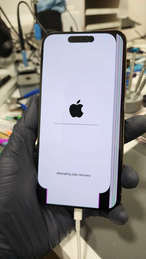
I had an iPhone 14 Pro come in for Data Recovery. It was smashed really bad.
After isolating everything, I found the phone had no shorts and boot sequence looked normal. Unfortunately, I didn't have any iPhone 14 Pro screens in stock to test with.
But I did have an iPhone 14PM screen that I bought on launch day to do the teardown video for my YouTube channel.
I had seen someone else say the 13 Pro and Pro Max were cross compatible, at least for data purposes. So I gave it a try & sure enough, it works!
Sure, the image is distorted and the touch is does not line up with the image, but at least it allowed me to get data off this phone.
Another thing i learned from this case: iPhone 14 Pro (and Pro Max presumably) will require the bottom board connected, otherwise it restarts every 3 min.
I have done extensive testing to see what parts are required to prevent 3 min restarts on my known good 14PM. I found the Prox Flex, Power Button Flex and Charging Port Flex, ALL are required to be plugged in to prevent restarts.
Although I never tested with just top board only.
Until yesterday. I found I couldn't get data off this phone because it was restarting with known good parts.
Not until I connected the bottom board, did it not restart & I was able to get the data.
I wrote the panic log codes on the Repair Wiki, so you guys can take note of them: https://repair.wiki/w/How_To_Fix_an_iPhone_14_Pro_That_Randomly_Restarts
So I hope you guys found this helpful! If you read to the end, make sure to hit that like button!
If you have a Seek Thermal Cam, you're missing out if you don't have a VCC Seek Stand: https://www.vccboardrepairs.com/buy-seek-stand
Injured Gadgets just got these back in stock, so get them while you can!
It can take us a while to build these out sometimes, so they're sometimes out of stock for a while, but we're working towards always having inventory ready to build more as they sell out.
This stand makes using a thermal cam so easy. So much better than any other thermal solution on the market.
It allows you to get real close up (using my Macro Lens), and easily find where the short is coming from.
Plus it's hard free, so you can have your hands free to try to boot the device from DCPS, while having an image that is in focus & not moving around.
You can even record a video through the app, while you inject voltage into the short, so you can go back & see exactly which component was it that was heating up.
Save yourself lots of time by getting a Seek Cam, Stand & Macro Lens! ...
Anyone who is doing game console repairs, knows how many screws you need to remove to access the motherboard.
Especially the PS5, with the 5,000 screws or so.
If you don't already have an electric screwdriver, GET ONE ASAP.
🌟 Cordless Screwdriver with T9 Bit: https://amzn.to/3E5duCj
🌟Extended T9 Bit: https://amzn.to/3c4YJac
It's rechargeable through micro USB and allows you to easily swap the tips out. You can also fold it to be straight or L shape.
Let me know below if you are already using an electric screwdriver 👇👇
This iPad Pro 11-inch had already been worked on, but the real problem wasn’t the port.
Using a USB-C PD meter and Mechanic USB-C tester, I was able to confirm abnormal charging behavior and trace the issue deeper into the board. The fault ended up being a failed CD3215C00 charging controller IC and TriStar.
After replacing the ICs, recovering the battery voltage, and verifying proper USB-C PD negotiation, the iPad returned to full 15V fast charging.
This is why proper diagnostics matter. The charging port is only one part of the circuit.
—
Repair techs: how often do you see charging IC failures after port damage?
—
Watch the full repair video here 👀:
Just posted a new iPad charging port repair video for techs dealing with base model iPads and Air/Pro variants with soldered dock flexes.
This iPad 7 was a classic life but no charge case. In the video I walk through:
- Confirming it’s a charging issue and not a no-power board fault
- Using a USB charging meter to verify current draw
- Verifying the port with the Mechanic Lightning tester
- Confirming dock flex failure with the Blue Tristar tester
- The soldering technique I use to remove and replace these dock flexes without ripping pads or damaging surrounding components
This design applies to multiple iPad generations, so the diagnostic and soldering process carries over to a lot of models.
Curious who still struggles with replacing these dock flexes without ripping pads?
🔥Full video breakdown of diagnosing and replacing a soldered iPad charging port:
Device came in water damaged after a previous repair attempt by another technician.
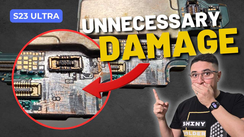
Board had scraped areas near the battery connector, unnecessary UV mask around multiple components, and incomplete inspection (main CPU shield was never removed).
Initial checks:
VPH power and VBAT lines not shorted
1V8 rail was hard shorted
Troubleshooting process:
Removed shields that were never taken off during the previous attempt
Removed charging IC due to questionable solder work
Removed a nearby IC that was still corroded underneath
Used DCPS + thermal camera to inject voltage and attempt to locate the short
Continued inspection and testing until no further progress could be made
At that point, proceeded with a full CPU swap:
CPU, RAM, UFS, and EEPROM transplanted to a known good board
Device booted and data was successfully recovered.
Full breakdown is up on YouTube. Link in the comments below


