I had this iPhone 12 Pro Max come in for Data Recovery.
It had corrosion near the power button connector, but it actually wasn't that bad.
The device booted, but it was in recovery mode. I would exit recovery mode with 3u tools but would still go back to recovery mode.
This made no sense. Why would water damage do this?
So I flashed an update & it went through successfully, 100% with no errors, but once again, it booted back to recovery mode.
This led me to think...
There was water damage near power button connector
12PM will go into recovery mode if the power button connector is pressed down all the time while booting
Maybe it has to do with the power button connector.
So I booted up the phone & measured the power button pin's voltage. It was like 0.6V.
If you know how power button lines work, they actually have a HIGH signal (1.8V in this case), and when that signal goes LOW (0V), that's how the device is told electrically, to process the power button being pressed function.
Therefore, if the voltage at the connector is stuck at 0.6V (essentially NOT 1.8V as it should be), that means the phone thinks the power button connector is being pressed down.
But it's not pressed down by anyone. it's shorted or failed where it can't be in a state where it has a HIGH signal.
So now it all made sense. The power button line (IO_BUTTON_SIDE_L_1V8) was bad.
Checking the schematics & ZXW, you can see that line basically is generated by the PMIC.
At this point, I have 2 options:
1. I replace PMIC & hope that solves it - it probably would. But that required splitting the sandwich & doing PMIC, which is super risky
2. Or... I feed it 1.8V from somewhere else & hope the voltage from the other 1.8v power source doesn't get pulled down by the short in the PMIC.
The first thing I tried was, jumping PP1V8_ALWAYS to IO_BUTTON_SIDE_L_1V8
Buuuut, then the device wouldn't boot anymore. It would hang at 20mA after prompt to boot.
At this point, I asked some friends about this issue. Sure enough, Aaron Harrington said he had a video on this exact issue, which i'll link in the comments.
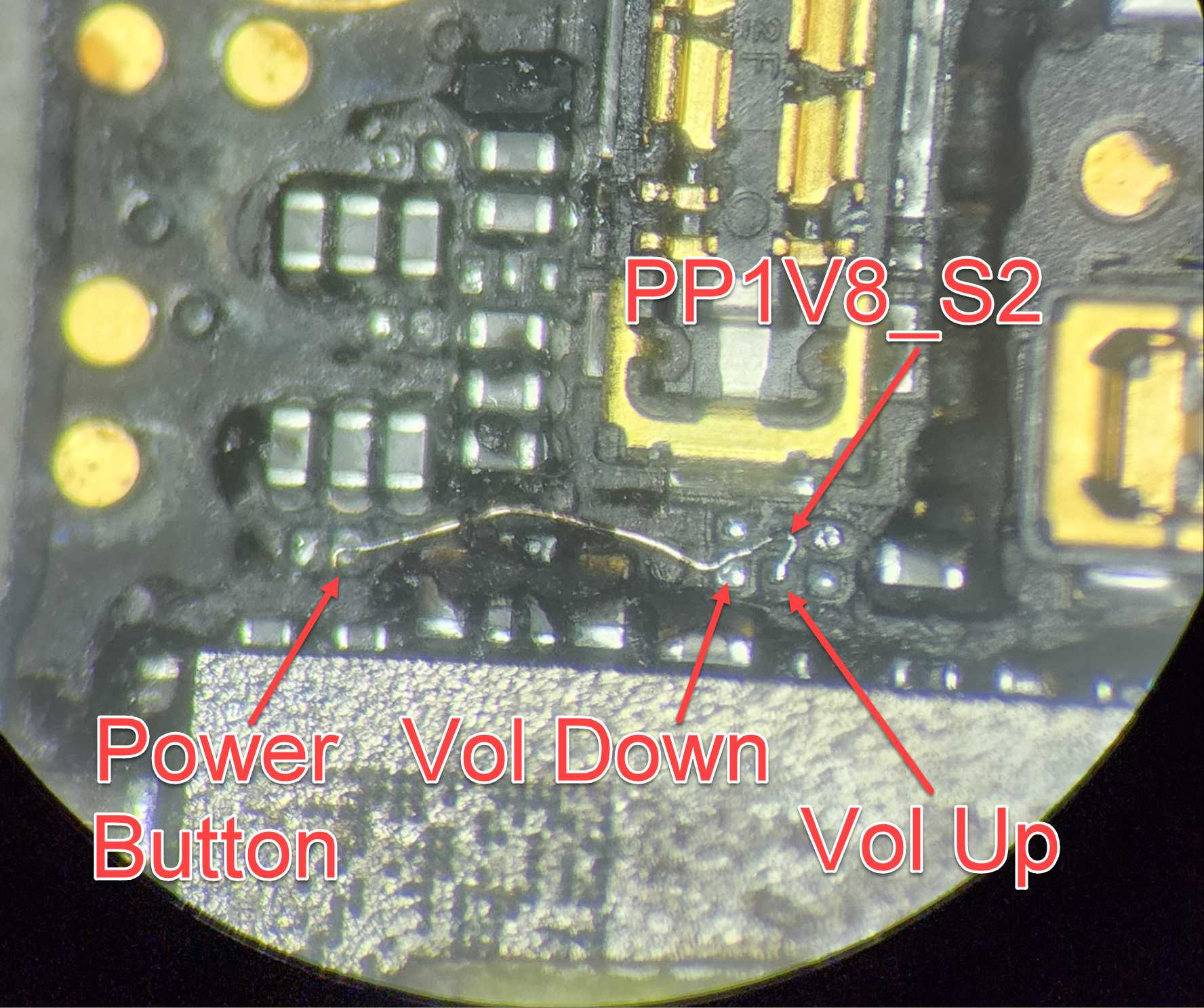
Basically, I needed to check the volume button lines as well, which sure enough, were also in a LOW state.
In his video, he jumped PP1V8_S2, which is in that same general area, to the Vol up, Vol down.
Then he jumped PP1v8_Always to power button line.
Not sure why it worked for him, but not me.
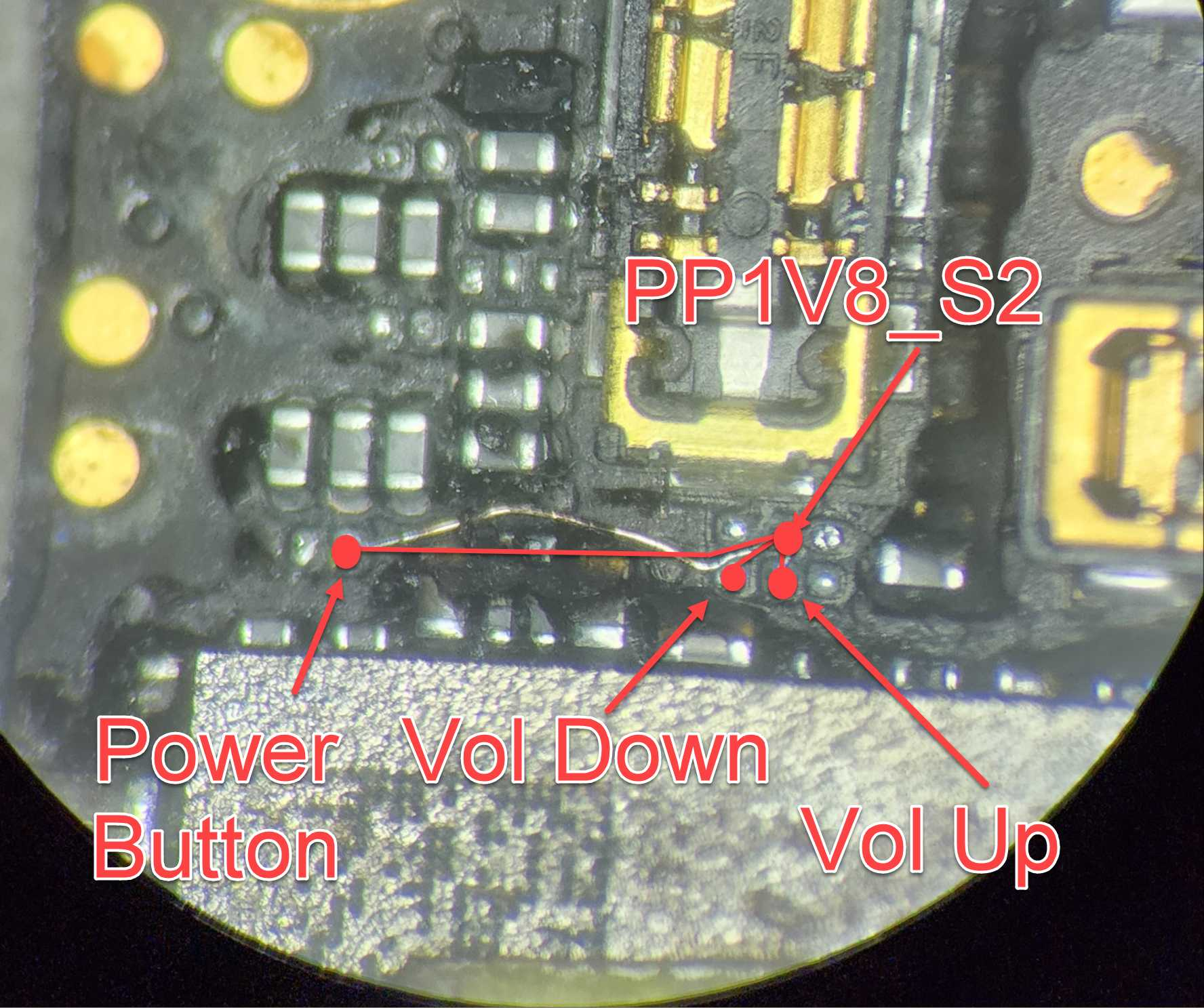
So I just decided to jump all 3 lines to PP1V8_S2
And BOOM, it booted! And I got the data! 🙌
So let me know.. what did you learn from this post? Let me know down below 🤔
If you have a Seek Thermal Cam, you're missing out if you don't have a VCC Seek Stand: https://www.vccboardrepairs.com/buy-seek-stand
Injured Gadgets just got these back in stock, so get them while you can!
It can take us a while to build these out sometimes, so they're sometimes out of stock for a while, but we're working towards always having inventory ready to build more as they sell out.
This stand makes using a thermal cam so easy. So much better than any other thermal solution on the market.
It allows you to get real close up (using my Macro Lens), and easily find where the short is coming from.
Plus it's hard free, so you can have your hands free to try to boot the device from DCPS, while having an image that is in focus & not moving around.
You can even record a video through the app, while you inject voltage into the short, so you can go back & see exactly which component was it that was heating up.
Save yourself lots of time by getting a Seek Cam, Stand & Macro Lens! ...
Anyone who is doing game console repairs, knows how many screws you need to remove to access the motherboard.
Especially the PS5, with the 5,000 screws or so.
If you don't already have an electric screwdriver, GET ONE ASAP.
🌟 Cordless Screwdriver with T9 Bit: https://amzn.to/3E5duCj
🌟Extended T9 Bit: https://amzn.to/3c4YJac
It's rechargeable through micro USB and allows you to easily swap the tips out. You can also fold it to be straight or L shape.
Let me know below if you are already using an electric screwdriver 👇👇
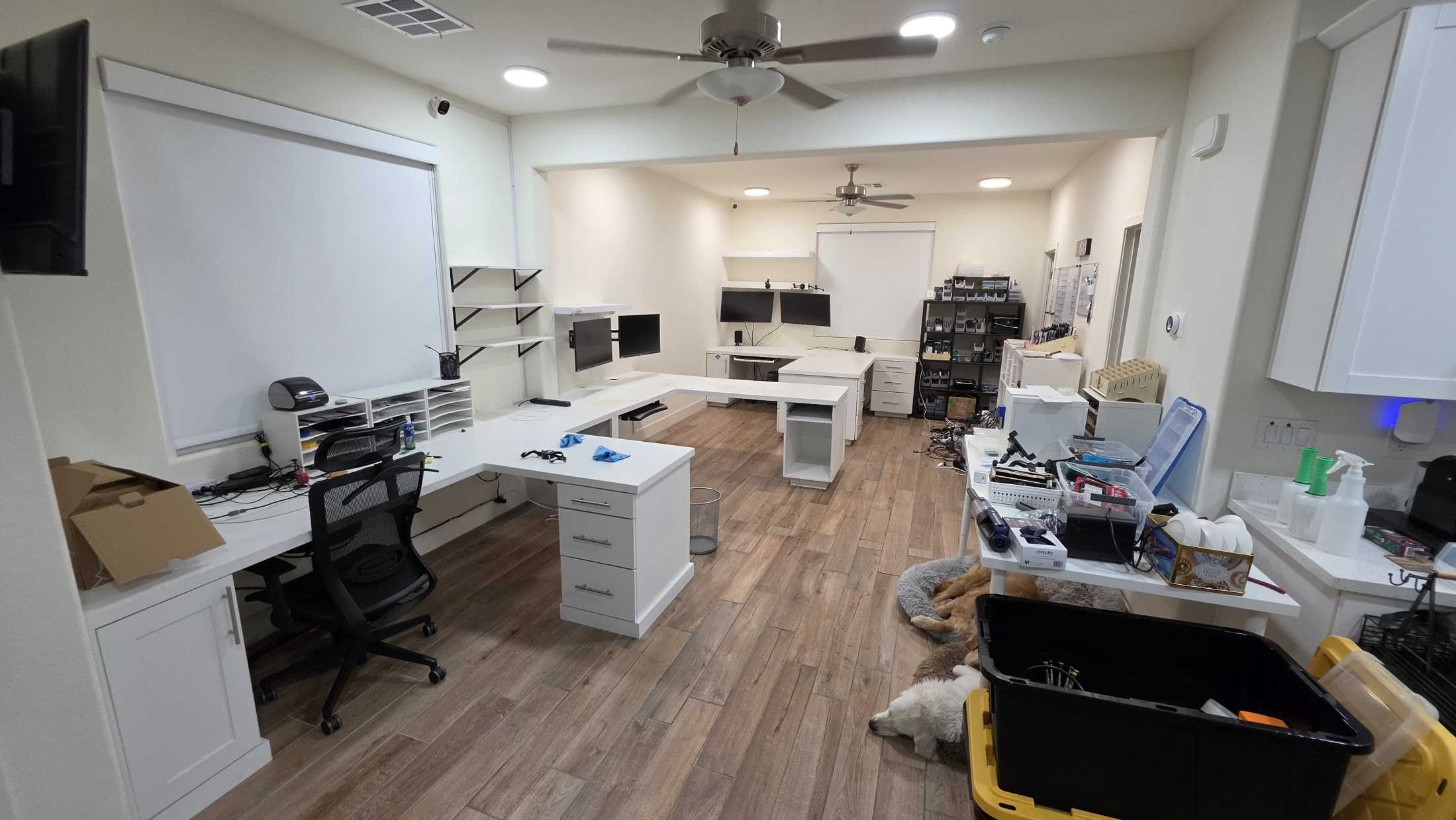
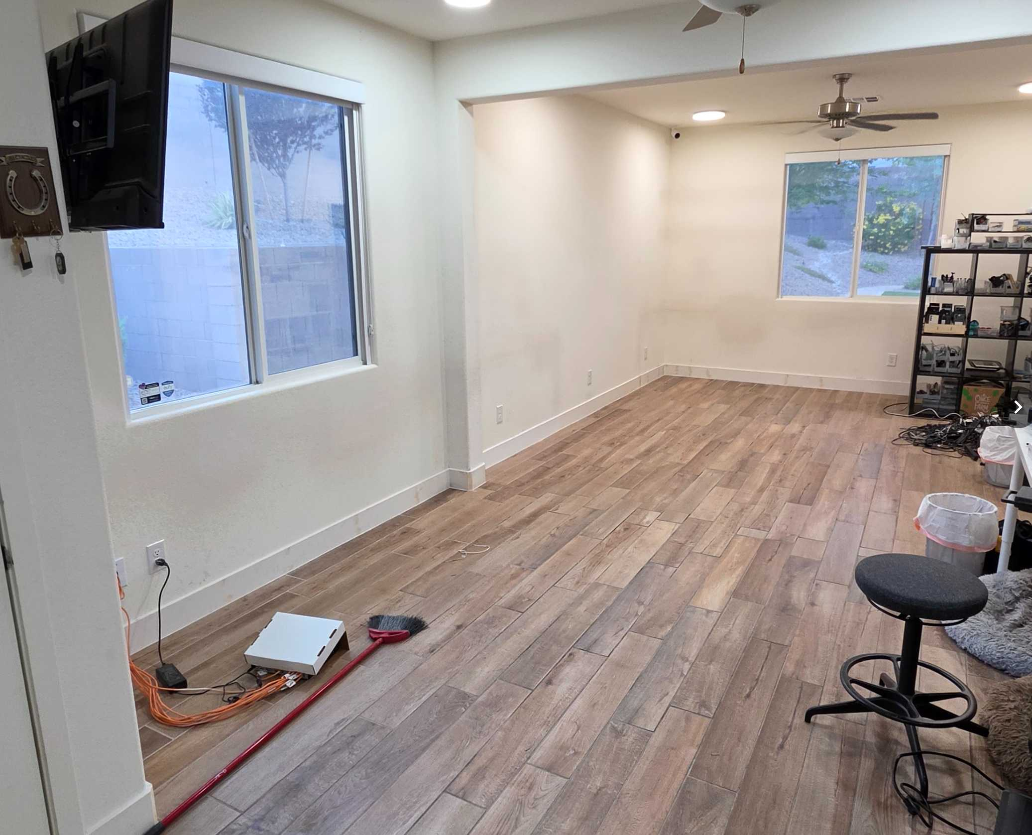
In case you haven't heard, I will be moving from Las Vegas, NV to Star, ID.
In my Las Vegas office, I had fully custom built workbenches for myself & my employee(s). But now it's time to go & tear everything down.
I'm really sad since these benches felt like the perfect layout! Or maybe I just got used to them.
I've attached some pics of what it looked like before & now that's all gone.
I do have some good news tho.... I recorded a detailed video of my office for youtube! I'll be posting that video soon!
Like this post if you want to see that video!
Hey guys! I'm so glad to finally get here. Thank you Jesse for the encouragement. Took me a minute but I'm here. I'm so eager to learn and grow. I have some experience with soldering etc, I can treat with obvious issues but there's something about diagnosing issues (especially with iPhones) that I have trouble with. I'm hoping this community can help with that.
Currently I have two iPhone 13 devices that need repair. One is stuck in recovery mode. A flash was attempted but there was an error during the process (Error 4013).
The other 13 does not boot or charge. It pulls 0.02A on the ammeter and I can feel both the back getting really hot. I tried this with two batteries. I also noticed that the wireless charging IC also gets very hot (338S00817) even when using a wired charger.
Remember I'm a noob so please....be gentle. Any help greatly appreciated. Thanks in advance!
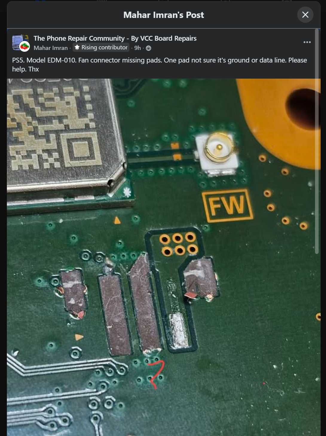
A funny example of why board repair are still very human skills.
Someone posted in my Facebook group asking for help identifying a ripped pad on a PS5 fan connector. The connector had been torn off the board, and they wanted to know what signal the missing middle pad belonged to so they could run a jumper.
A commenter decided to let AI handle it.
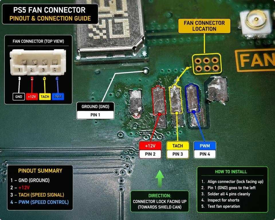
They fed the photo into ChatGPT and got back a nice-looking annotated diagram showing all the pin functions. The problem?
It was completely wrong.
The AI labeled the missing pad as the TACH signal when in reality that pad is ground.
The scary part is that if you didn't already know the answer, the diagram looks convincing. It has arrows, labels, colors, callouts, and all the confidence in the world. Yet it still gave bad information that could send someone down the wrong path.
This is one of the reasons I don't lose sleep over AI replacing board repair technicians.
AI is incredibly good at summarizing information that already exists publicly. But in...